Laser particle size calibration method based on photoelectric response characteristics
Laser particle size calibration method based on photoelectric response characteristics
Wang Shaoqing Ren Zhongjing Zhang Yong Zhang Ximing He Fang
(Laser Application Research Institute, Shandong Institute of Building Materials Industry) Jinan 250022)
Abstract : The photoelectric response characteristics of laser particle size analyzer are studied experimentally. Based on this, a new calibration method is proposed. The correctness of the method is verified by experiments.
Key words : laser puller particle size analysis photoelectric response
Abstract: A new method has been developed to calibrate laser particle sizer based on the exeperimental study of its photo-electric response characteristics. Measurements which have been made demonstrate the effectiveness of this method.
Keywords: laser particle sizer, particle size analysis, photo-electric response
Laser particle size analyzers have received increasing attention in powder particle size analysis. The heart part is the photoelectric conversion system. The measurement principle is shown in Figure 1 .

The laser is expanded by a collimation system C to illuminate the sample window S carrying the particles to be tested with parallel light , and the scattered light of the particle group is received by the Fourier lens L , and the ring array is used for photodetection on the back focal plane of L. D is receiving the particles scatter spectrum, and then converted into a photocurrent by the electronics system E for the I / V conversion amplification and a / D conversion, into the computer for analysis processing to obtain particle size distribution of the test sample.
It can be seen that one key to ensure the accuracy of the laser particle size measurement is the correct response of its photoelectric conversion system. The criteria for correct response of the photoelectric conversion system should include the following two:
1 ) The response of each unit is linear;
2 ) The response of each unit is consistent.
Calibration of the laser particle size analyzer is a linear and uniform correction of its photoelectric response characteristics. At present, there are a variety of calibration methods [1 , 2] , but there are deficiencies, which can be summarized as follows: First, the physical meaning is not clear, second, the operation is more complicated, and third, the scope of application is limited. Based on the experimentally measured response characteristics of the laser particle size analyzer, the author proposes a new calibration method. The method has clear physical meaning, simple operation and is suitable for calibration of various multi-unit photoelectric conversion systems.
Response characteristics of laser particle size analyzer photoelectric conversion system
The method for measuring the photoelectric response characteristics of the laser particle size analyzer is as follows: a circular array photodetector of the laser particle size analyzer is irradiated with a uniform and stable light source, and the power of the light source is monitored by a standard optical power meter. The light intensity output I of each unit of the photoelectric conversion system is recorded under various light intensities of 1o , and each I - Io curve is obtained, and the response characteristics of each detecting unit are obtained.
The experiment found that the response of the laser particle size photoelectric conversion system has three characteristics:
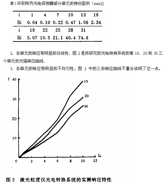
1 . Under uniform light illumination, the light energy response of each unit varies greatly. The experiment uses a 12 -bit A/D converter. When the output of several external channels has reached the saturation value of A/D of 4095 , there is no obvious response in the innermost way. This is due to the large difference in the receiving areas of the inner and outer rings of the annular array photodetector. Table 1 shows the receiving area of ​​some of the 31 detection rings of the detector , which is nearly two thousand times different from the area of ​​the smallest ring.
Method for correcting photoelectric response characteristics of laser particle size analyzer
Based on the measured response characteristics and the two criteria for correct response, the correction is performed in two steps.
1 . The non-linear correction of the response characteristics of each unit is to correct the response curve of each unit to a straight line to ensure its linear response to incident light. At this point, different correction methods can be taken depending on different usage requirements. If, in use, the response of each detector unit may vary from minimum to maximum, the linear response must be guaranteed over the entire measurement range, ie the entire response curve is corrected to a straight line. If the detection unit only works in a small dynamic range, it is only necessary to correct a response curve corresponding to the range to a straight line, which is simpler and more accurate than the whole process. In the laser particle size analysis, since the scattered light of the particle group is weak, the light energy received by the photodetector is small, so the response of each unit of the photoelectric conversion system is small. From the measured response curve 2 , it can be seen that when the light intensity response I is less than a certain value, each detection unit has a good linear response. Therefore, a limited range of fitted straight lines can be used to represent the response characteristics of each unit. 3 is the input light intensity I. < Light intensity response of the 10th , 20th and 30th units at 4000 hours ,
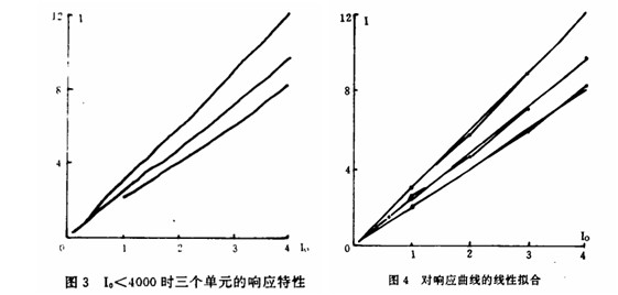
The linearity is better. Figure 4 is the result of straight fitting them. These lines are the linear response characteristics of the corrected units. The slope of the fitted line is called the responsiveness of each unit. The responsiveness of each unit of the visible light electrical conversion system is not uniform.
2 . Non-uniformity correction for responsiveness of each unit
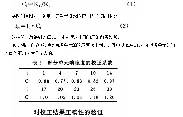
After obtaining the linear fitting straight line of each unit, it is very simple to make the non-uniformity correction. Just correct all the straight lines with different slopes to a certain straight line. The specific method is as follows: Let Ki denote the slope of the fitted line of the i- th unit, K . For the slope of the reference line taken, the responsiveness correction factor for the ith element is defined as
To verify the effect of the calibration, two verification experiments were performed.
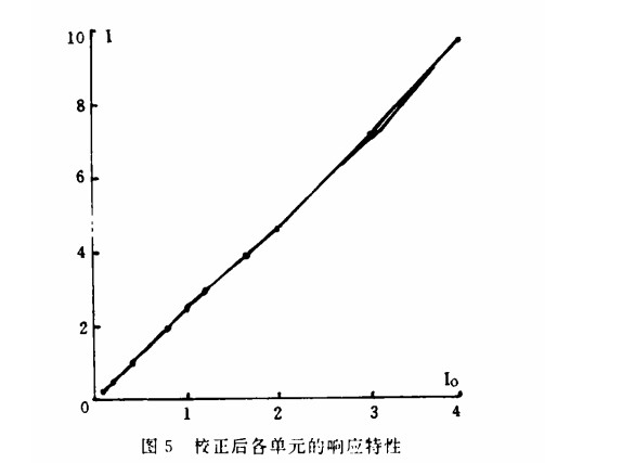
First, the annular array photodetector is irradiated with uniform light of different intensities , and the 10th , 20th and 30th units are still taken , and the light intensity response is corrected according to the formula ( 2 ), and the response curve is obtained. The result is shown in Fig. 5. . Visible corrections have achieved the intended purpose.
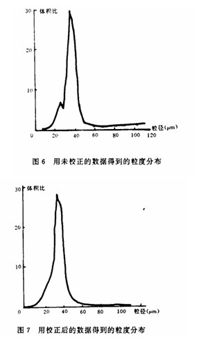
The second is to compare the measurement results of the same powder sample. First, the output signal of the photoelectric conversion system is not corrected, and the particle size analysis is directly performed. The obtained result is shown in Fig. 6 . There is an undue "double peak" distribution and "hook-tail" phenomenon. Then the group of signals is corrected by ( 2 ) and then subjected to particle size analysis. The results are shown in Fig. 7. "Double peak" and "fin tail" disappeared. Explain the correctness of the calibration method and calibration results.
The focused intense pulsed laser can generate local high temperature in the micro-area of ​​the metal surface and ionize the evaporated gas. Hydrogen ions and other elemental ions rapidly leave the zero-potential metal target surface under a strong electric field in a vacuum of 1.3 × 10⁻⁴ Pa to reach a high-pressure aluminum filter membrane. These incident ions reaching the filter membrane collide with atoms in the amorphous aluminum film. According to LSS theory, there are two ways of energy loss:
1 ) The incident ion collides with the nucleus in the solid, which is called nuclear block, and its stopping power is represented by Sn . Value regardless of the incident ion energy E.
2 ) The incident ions collide with electrons in the solid. Called electronic blocking, its stopping power is represented by Se(E ).
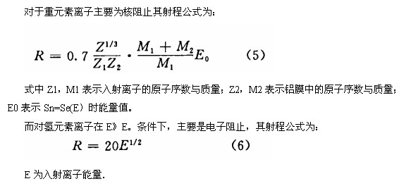
According to the literature ( 5)(6 ), when the voltage of the various elements contained in the steel target (zero potential) is negative and the voltage on the filtered aluminum film is negative 104 volts, the hydrogen ion has a range of 200 nm in the aluminum film and the carbon ion range It is 100 nm , and other elements with larger atomic numbers have a range of 1 to 10 nm in the amorphous aluminum film and much less than the range of H+ in aluminum. It can be seen that only hydrogen ions with an energy higher than 104 eV can penetrate the 200 nm aluminum film to generate secondary electrons at a few nm of the back side of the film . Only these secondary electrons are guided by a strong electric field to a zero-potential aluminum-plated scintillation body. Then, the recording is amplified by a photomultiplier tube to obtain information on the hydrogen ion concentration at the measurement point on the surface of the steel target.
We applied a laser-filtered mass spectrometer based on pure physical process plasma measurement method. The hydrogen ion counts in the weld zone and the transition zone of the weld profile were measured and the hydrogen ion counts in the non-melting zone were measured. The ratio is called the relative hydrogen index. D. A tester for measuring the average unit mass average concentration in steel samples by hue chromatography using vacuum heating to drive out the steel. Thus, the micro-region hydrogen content can be calculated. Using this method, we report the determination of the hydrogen distribution of U -shaped prestressed elbows made of A3 carbon steel and ICr18Ni9Ti stainless steel in the literature [7] . It has also reported the points on the joint sections of these two types of steel. The distribution of relative hydrogen index [8] provides a numerical basis for the study of hydrogen brittle fracture mechanics.
We named this analytical method based on the plasma generated by focused intense pulsed laser and then analyzed its physical and chemical processes as plasma metrology. Laser plasma metrology has a wide application field. It is a new analysis of applied lasers. method. In theory and practice, further improvement and development are needed.
references
[1]Lee G.. Dodge , APPLED OPTICS , 1984 , ,23
[2] Wang Shaoqing, Wang Jiaofang , Applied Laser, 1981 , 11.172
L Tryptophan,L Tryptophan Powder,L Tryptophan 73-22-3,Feed Grade L Tryptophan
CHANGZHOU GUANGHUI FOOD INGREDIENTS CO.,LTD , https://www.gsweetfood.com